
The battery pack leak detector is an air leakage tester based on the differential pressure method.
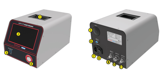
The device has a compact all-metal case and interface, which is solid and durable. With WIFI module, it is helpful to connect the device and the information system of users’ company, and it is convenient to record and export the relevant test information in real time.

Safety Precautions
Application Range
The xLD-C is a precision testing equipment that uses compressed air to test the leak of products.
Safe Use Instructions
This chapter describes the safety precautions to be taken during the use. Please read safety precautions carefully before use. For details about the installation and operation procedure, refer to the warning in the corresponding chapter. Device damage is not covered by the warranty if the installation and operation is not performed according to the instructions in this manual.
Manual Keeping
The user manual is an integral part of the product.
This manual contains important information about how to operate the device. Read this manual carefully before performing operations. Strictly follow the instructions in this manual to operate. Otherwise, device damage, personal injury, and property loss may occur.
WARNING
The use environment and storage method have a certain impact on the lifespan and reliability, please pay attention to avoid long-term use in the following working environments:
√ With high, low temperature and humid beyond the technical specifications;
√ Places with direct sunlight or near heat sources;
√ Places with dust, corrosive substances, salts and combustible gases;
√ Vibrating, impact-prone places;
√ Where rain water can drop onto the device;
If long-term storage is not suitable, the device must be stored in a dry environment, the standard storage temperature range is: -5-50 ° C (23℉-122℉).
NOTE
Do not disassemble the device without the authorization of the maintenance engineer, otherwise we will not be responsible for all unfavorable consequences.
Body Identification Protection
Do not tear, damage, or change any warning and caution labels on the device.
Do not destroy, damage, or change any part number or port identifier on the device.
Do not destroy, damage, or change any markings or tamper-proof label on the device.
Component Electrostatic Protection
Do not touch any circuit board or other electrostatic sensitive components in the device when the operator is carrying static electricity. Clear the static electricity and wear an ESD wrist strap before touching.
Other Protection
Avoid direct sunlight on the device.
Protect the device from corrosive gases or liquids.
Take necessary protection during equipment operation, maintenance, or transportation.
Test Preparation
Operation Requirement
WARNING
Before operation, thoroughly check the operating environment of the device again:
√ The tester should be placed with little dust and impurities as far as possible.
√ Place as close to the product as possible to reduce pipe volume.
√ The device is a countertop, directly placed on the desktop or shelf, please pay attention to reserve enough space for tube connection, testing and maintenance.
Check and Test the Air Source
Check whether all cables are connected. Set the pressure reducing valve to the lowest setting and connect the air source to the test air inlet of the tester. Pay attention to the air supply capacity of the air source, if the flow rate is too low, the device will appear slow inflation or low-pressure alarm.
For optimal test performance, it is recommended the pressure of the test air source be at least 200kPa greater than the maximum test pressure.
Check the Drive Air Source
There are clearly requirements for the pressure range of the driving air source. The required pressure should be provided in accordance with the instructions on the label to ensure normal operation.
NOTE
For air control valve models, the fluctuation of the driving air source exceeds the required range will lead to fluctuations in the test data, if the pressure of the driving air source does not meet the minimum requirements, the tester will not work properly.
Start
The External AC Power Supply Connection
Tube Connection
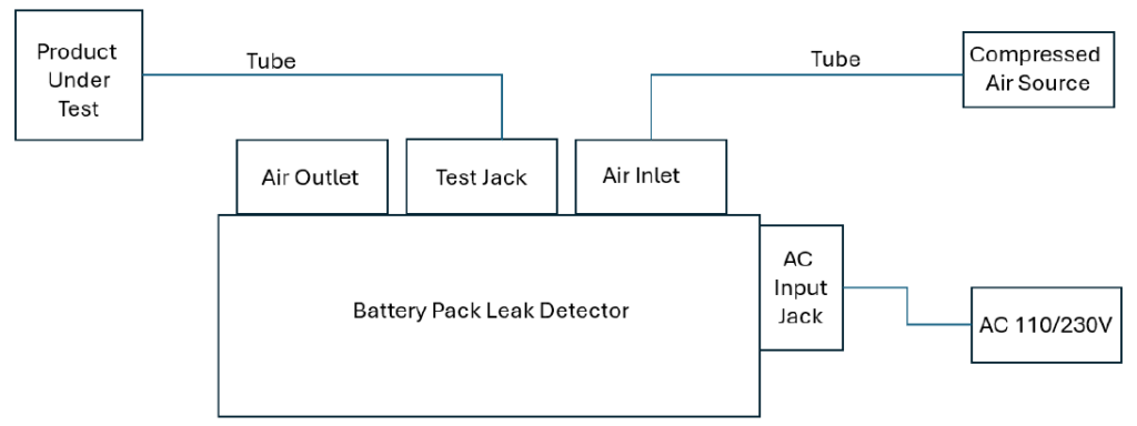
It is recommended to connect the product under test to the test jack in the figure above using a high-quality ferrule joint and a rigid air tube.
Steps for Connecting the Air Source
- Take out the air tube, one side is with a C-type self-locking connector.
- Align the other end of the air tube with the air inlet connector on the device and remove the
nut from the air inlet connector. - The nut of the air inlet connector on the device is placed on the air tube.
- Cover the air tube on the air inlet connector of the device to ensure that the connection is
secure. - Use a tool to tighten the nut and ensure that the nut is securely connected.(Recommended to use a 14-inch fixed open wrench or an 8-inch adjustable wrench).
NOTE
In the test loop, the requirements for air tightness should be very strict. It is recommended to connect the tube with a ferrule joint to ensure that there is no leakage at the joint. For nontest circuits, air tightness requirements are slightly lower. For example, the test air source inlet and the drive air source inlet can use a commonly used quick connector.
If we use a soft air tube, such as a silicone tube, the pressure drops generated when the product under test is leaked will be compensated, resulting in greater interference and wrong judgment because of the tube deformation.
WARNING
If it is found that there is dirt around the outlet port, it is necessary to check the sealing of the tester. The dirt may lead to problems with the sealing of the valve, resulting in a decline in tester performance or failure, affecting the quality management of the user.
Air Outlet Inspection
Avoid dirt and blockage around the outlet port to affect the exhaust.
Use a plug to plug the high-pressure connector and tighten it.
Use a plug to plug the low-pressure connector.

Remove the vent valve bolt and install the test connector. The test connector must be installed smoothly without air leakage.
NOTE
If a second leak test is required, remove the vent valve bolt and exhaust.
If the first test fails, retest after passing the test.
It’s ok if the third test is still passed. If it fails, check the air leakage position, and reinstall or replace the relevant parts after the air pressure inside the body is emptied. The test interval will last until the pressure inside the capsule is drained.